Continuing the previous post and following LearnOpenGL, this time I started implementing Normal Mapping.
Advanced Lighting—Normal Mapping
This section introduces the principles and implementation of the familiar normal map.
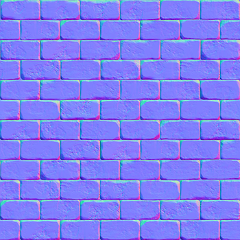
Normal maps are usually blue because the default surface normal points along the Z axis (the B channel), so the B value is the largest of the RGB channels. A bumpy surface offsets the normal toward the x and y directions by different amounts, producing a texture like the one above.
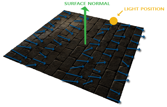
Treating the sampled normal-map value as a world-space normal causes a calculation error because not every surface faces world-space Z. In the example above, the surface faces the Y direction. The Z in this normal map is therefore not world-space Z; it is the Z axis of tangent space. Tangent-space Z is the normal direction of each triangle on the model.
Calculating the TBN matrix
To convert a normal map from tangent space to world space correctly, we need a matrix. This brings back the idea from the LookAt matrix in the camera implementation:
If we use three mutually perpendicular vectors (right, up, and front) to make a matrix and multiply it by the translation matrix of the current coordinate, we can transfer that coordinate into any space.
The matrix we need is a LookAt matrix that converts tangent-space coordinates to world space. The three mutually perpendicular vectors required to construct it are Tangent, Bitangent, and Normal, so it is generally called the TBN matrix. The original tutorial also implements a manual method for calculating these vectors, but I was lazy: when importing the model with Assimp, I enabled the flags that calculate each vertex’s Tangent and Normal and put both into the GL_ARRAY_BUFFER for use in the shader.
Unity’s default model-import settings expose tangents and normals. In a custom shader, declare the attributes and they are available; in Shader Graph, using the relevant node generates them automatically.
Because Assimp already calculates the tangent and normal when importing the model, the Bitangent is simply the cross product of T and N.
After calculating the TBN matrix in the vertex shader, sample the normal map in the pixel shader and transform the result to world space. The lighting model then needs no extra handling.
The conversion above is equivalent to Unity shader code’s built-in TransformTangentToWorld in SpaceTransforms.hlsl.
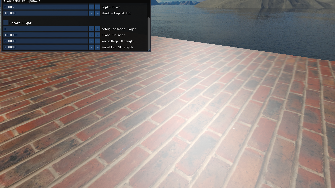
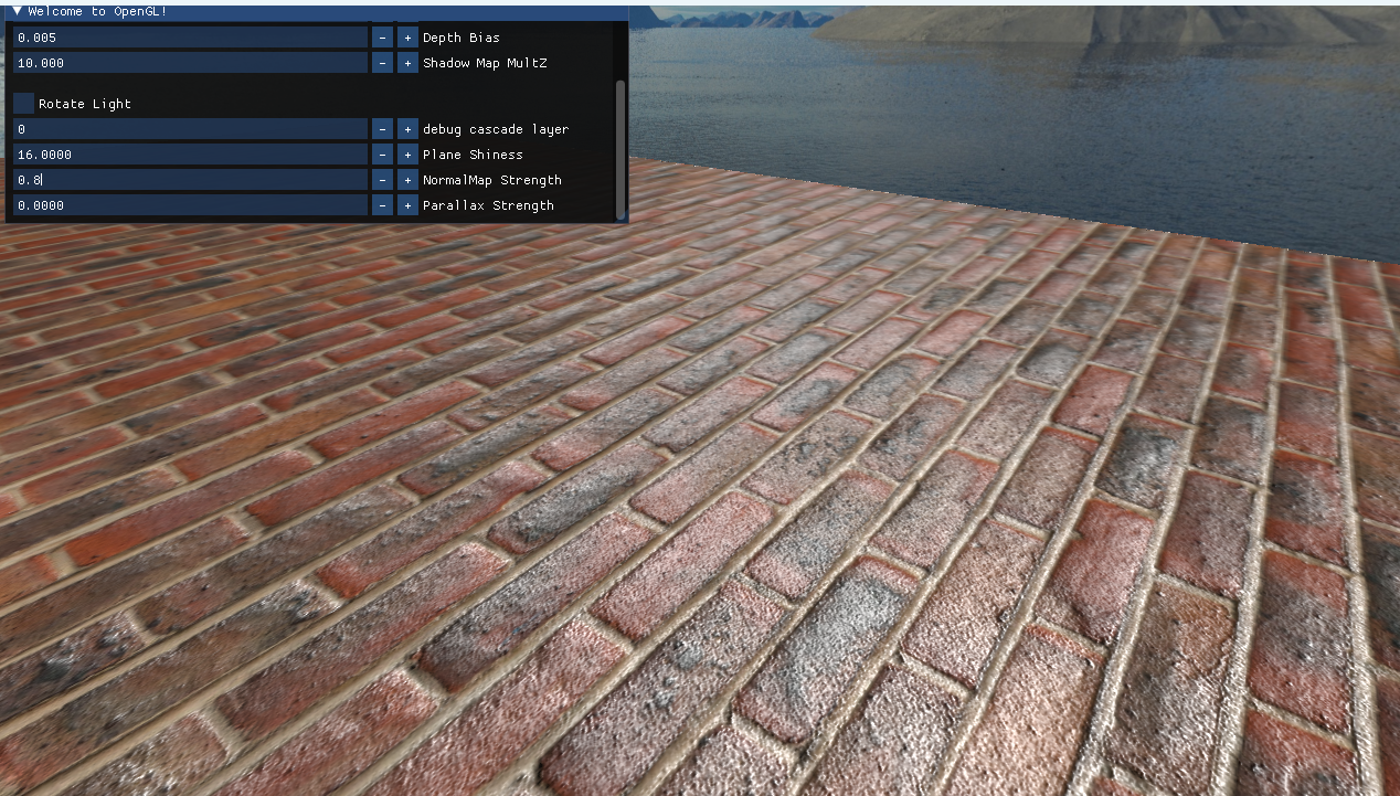
Here is the difference before and after implementing normal mapping in OpenGL.
Parallax Mapping
Normal mapping alone sometimes does not produce enough apparent surface relief. This section introduces parallax mapping, which creates more pronounced height variation but has usage limitations and a performance cost.
Principle
Parallax mapping’s relative, height-map-based technique is displacement mapping, commonly used in terrain systems. High-quality displacement mapping requires a very large number of polygons or tessellation, while parallax mapping does not. It creates the illusion of relief simply by sampling a texture.


Suppose there is a plane. For a given pixel, the point where the observer looks at the plane is A. In a height map that stores surface height variation, the corresponding point should be B. The key to parallax mapping is to offset the sampled height-map UV along the yellow view direction in the image, making the final sample approach B. I find this fascinating.

The offset depends on the height sampled at point A. When the height map has dramatic height changes, the offset point can be far from the ideal point B, producing jagged edges.
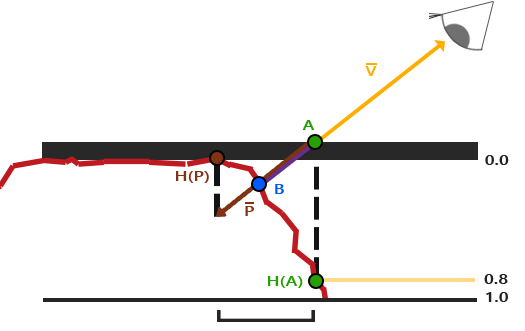
Also, for a pixel shader rendering a mesh, portions of a plane that are not on screen after rasterization are not displayed. Unlike displacement mapping, which lifts each vertex, parallax mapping treats the height map as a depth map pushed downward during calculation. The parts that appear raised on screen are actually below the plane, within the region covered by the rasterized plane.
Calculating the inverse of TBN
The view vectors in the diagrams above are in tangent space (the view direction relative to each triangle surface). To obtain the view vector, use the inverse of TBN to transform the world-space view direction into tangent space.
The axes in the TBN matrix are mutually perpendicular and normalized, so the transpose of TBN is also its inverse.
Unity provides a
TransformWorldToTangentfunction for this.
Improving parallax mapping
Multiple samples
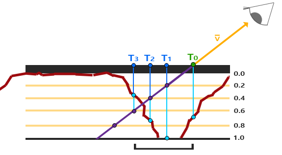
Offsetting UVs from one height-map sample produces a large error when the height difference is obvious or the plane is viewed from a nearly horizontal angle. Methods that take multiple samples to find the closest point were developed to solve this. Parallax occlusion mapping is one of the techniques derived from multiple sampling.
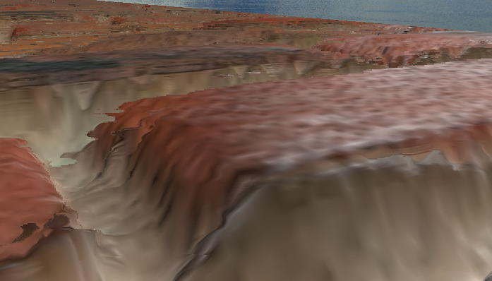
The disadvantage is that even with too few samples there is still obvious aliasing (the bricks in the image look stacked like pancakes), while a large number of samples is expensive.
I tried following the LearnOpenGL implementation. Even with a high sample count (30+), I still saw a lot of aliasing in my scene, so I gave up and copied Unity’s implementation instead. The result was much better.
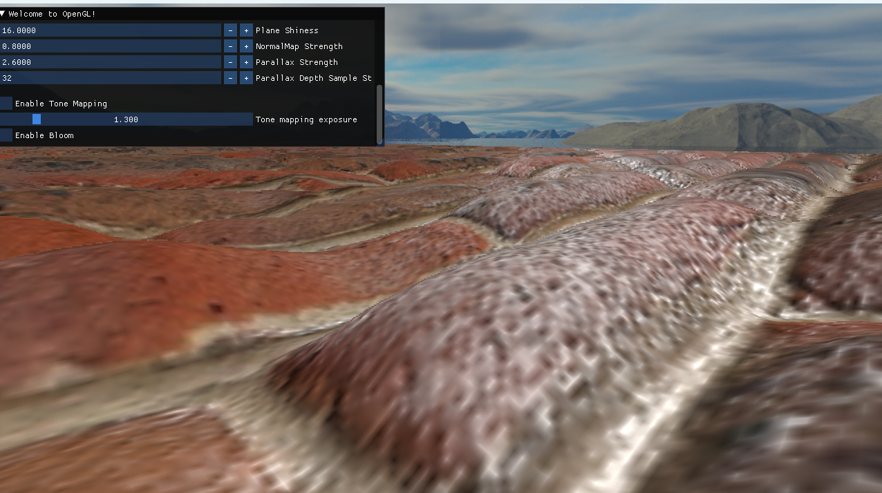
Unity’s Parallax Mapping + Faster Relief Mapping (32 samples) still looks good at extreme angles.
Aliasing and performance optimization
The sample count for parallax mapping does not need to be fixed for every pixel. It can be controlled by the angle and distance between the pixel and the camera. A camera nearly parallel to the plane needs more samples; a camera looking vertically down needs very few. A far-away object also does not need many samples.
The sampled height map is also important. As mentioned above, dramatic height changes are the main source of error. A small trick is to blur the height map. This smooths out the dramatic changes; fine details can be added with normal mapping, while parallax mapping handles the broad relief.
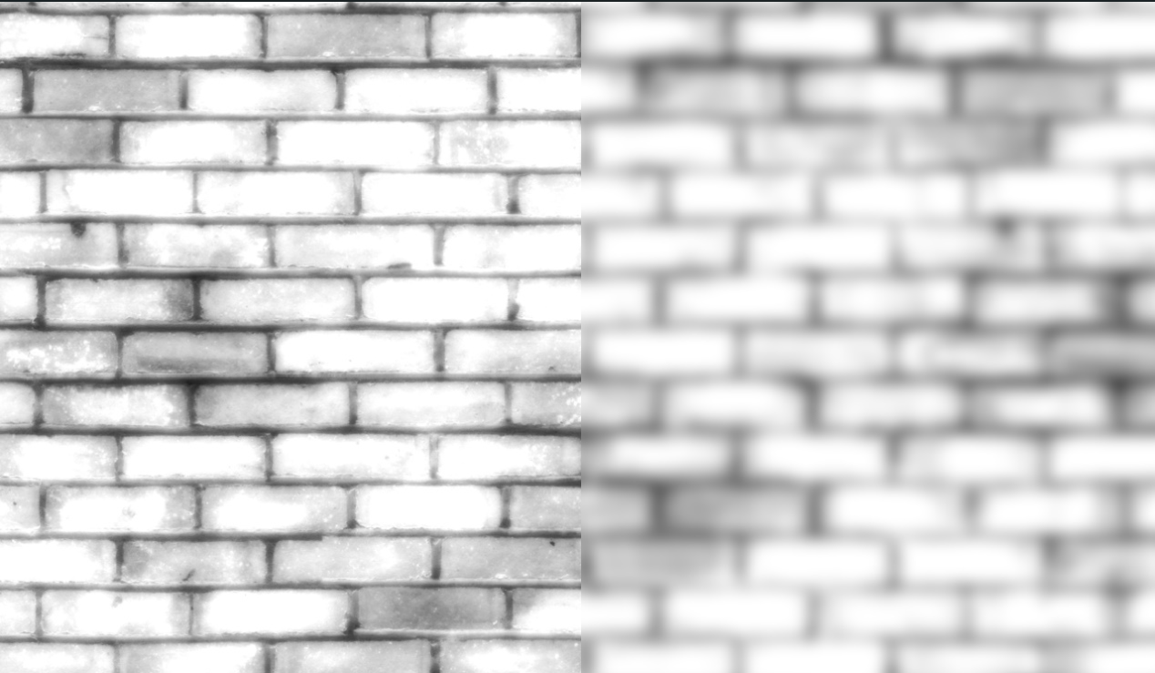
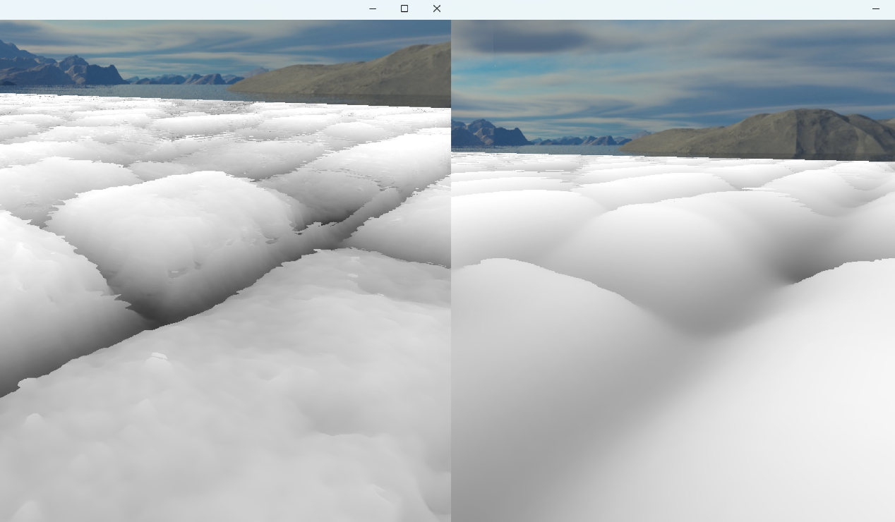
When the height boundaries are sharp, aliasing is more likely. Moderate blurring reduces it (I blurred mine a little too much. XD). Blurring is easy: apply a Gaussian-blur filter in Photoshop or another tool, and check that the blurred edges remain seamless.
This technique is based on a Unity technical-artist video.
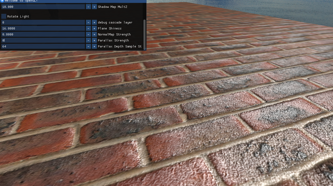
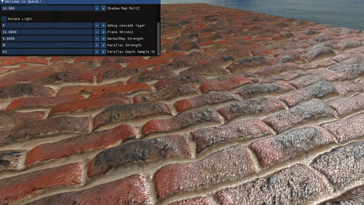
Finally, here is the floor with only normal mapping and with parallax mapping added.
Conclusion
When I previously wrote custom Unity shaders, I always copied the official code for normal maps, so I had never implemented it myself. This was a good opportunity to review the fundamentals. Now that I am familiar with TBN, I can also clean up the normal-map code in my custom shader; Unity’s Lit shader has many local keywords splitting that code up, which makes it a little messy.